
Pradeep Singh | 3rd April 2016
 ESP8266 has rocked the Internet of Things world. It’s a great module when it comes to IoT experiments, but setting it up for the first time could cause headache. Let’s try to make initial setup a little easy for you with this tutorial.
Prerequisites:
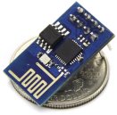
ESP8266 Module
USB to TTL UART Serial Converter Module
Bread Board with Male to Female Jumper Wires
Computer with Windows OS and Internet connection
1. Install Firmware for USB to UART Serial Converter
Once you have everything ready check if your Computer can detect USB to Serial Converter Module. If not, you need to install right firmware for it. For this tutorial I am using CP2102 USB to UART Bridge Controller manufactured by Silicon Laboratories. If you are also using the same module, you can download the firmware from manufacturer’s website (Link).
Once your USB to Serial Converter is successfully installed, you should be able to see a Com Port attached to it in Device Manager. Make a note of Com Port assigned to this module, you will need it later for flashing firmware.

2. Connect ESP8266 with USB to UART Serial Converter
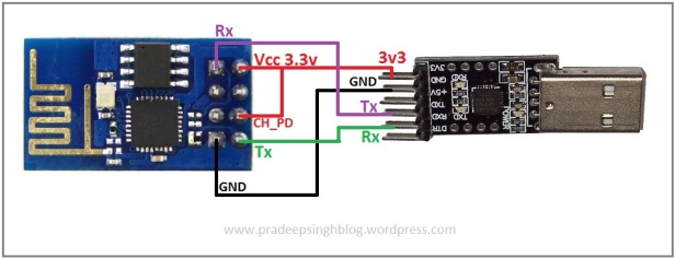
After installing USB to Serial Converter you are ready to move to next step. Connect the ESP8266 to your USB to Serial Converter as shown in following image –

As there is a link from Vcc Pin to CH_PD and GPIO-0 to Ground Pin on ESP8266, you may want to use Bread Board with jumper wires to making all the connections easily.
3. Download ESP8266 Firmware and Flashing Tool
There are several options available for ESP8266 in terms of Firmware and Flashing Tools. To keep things simple, let’s use NodeMCU Firmware and Flasher. You can download these from following links –
NodeMCU Firmware Flasher Download
4. Flash ESP8266 with Firmware
Now you can start flashing the firmware to ESP8266 Module. If you are using NodeMCU Flasher, you can follow the instruction given at Link.
Once the Flasher starts pushing the Firmware file to ESP8266, you will be able to see the progress in progress bar –

After the flashing process completes, remove the USB to UART Serial Converter Module from your Computer’s USB Port and plug it back after 5 seconds.
5. Change the Connections
Now your ESP8266 is ready with firmware. To start programming this module you must remove the connection between GPIO-0 and Ground Pins. Make sure all your connections between ESP8266 and USB to UART Serial Converter Module are same as shown in following image –
6. Download any IDE and Start Programming
Once again there are many options when it comes to the tools/IDE to program ESP8266 Module. Here in this tutorial we used NodeMCU Firmware and for this I found ESPlorer to be very good. You can download it from ESPlorer Website or directly from GitHub Repository.
7. Hello ESP8266
Let’s test this module with a simple program using ESPlorer IDE. Open ESPlorer by clicking on “ESPlorer.jar” file and perform following actions. For easy reference I have attached a screenshot of ESPlorer IDE and added some numbered labels along with blue boxes.

(1) Select correct Com Port and click on “Open” button on ESPlorer (In this Screenshot the button label is showing “Close” as we are already connected on Com port).
(2) You should be able to see “Got answer!” output on console if you are connected to correct Com Port.
(3) Click on “Snippets” button and click on “Edit Snippet0”.
(4) Add “print(wifi.sta.getmac())” to Snippet0.
(5) Click on “Run” button.
(6) You should be able to see MAC Address of ESP8266.
Congratulation! you just made ESP8266 work.
