
Pradeep Singh | 28th March 2016
![]()
ESP8266 is a great module for IoT and DIY project specially because of it’s compact size and low-cost. However this module works at 3.3v DC, which is not as easy to find as compared to 5v DC supply. So, let’s find out how can we make a very simple 5v to 3.3v step down regulated power supply module.
Quick Demo:
What do u need?
AMS1117 – 3.3v Voltage Regulator (SOT-223)
100µf Electrolytic Capacitors – 2 Pcs
Bread Board with Jumper Wires or General Purpose PCB
5v-12V Power Supply
AMS1117 – 3.3v Voltage Regulator:
The main component for this project is AMS1117 (SOT-223) Voltage Regulator. It is designed to automatically maintain a constant 3.3v output voltage and up to 1A output current.
 AMS1117 – 3.3v Voltage Regulator SOT-223
Putting Things Together:
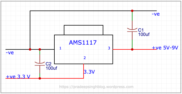
Connect the AMS1117 voltage regulator with 100µf capacitors as shown in following schematic. Larger capacitors (>100µf) can be used to further improve stability and transient response of MS1117 Voltage Regulator.
MS1117 Voltage Regulator is protected against short-circuit and thermal overloads. It supports input voltage range from 4.6 to 15V.
ADDITIONAL INFORMATION
Decoupling Capacitor with ESP8266 Modules:
ESP8266 is very sensitive to improper power supply. For better stability during different power conditions use decoupling capacitors as close as possible (within 1/2 inch) to ESP8266 power pins (VCC and GND). In following schematic you can see double decoupling capacitor with ESP8266 module.

It’s not uncommon to use two or more different-valued, even different types of capacitors to bypass the power supply, because some capacitor values will be better than others at filtering out certain frequencies of noise.
Facing Reset Issues?
ESP8266 is infamous for its weird reset issues. In most of the cases, the resets are caused by Power Supply related problems. You must take care of following points while powering your ESP8266 module –
- Make sure the power supply is capable of providing enough current to ESP8266. A regulated 3.3V source of at least 500ma is essential. If you are using other components like sensors etc, go above 500ma based on peak power requirements. It is always recommended to have some buffer while calculating the power requirements.
- Try putting a large capacitor (suggest using 470 uF) across the Vcc to Gnd rails on your breadboard or PCB. It will minimise reset inducing voltage fluctuations.
- At least a 10 µF decoupling capacitor as close as possible to the module specially if you have long power cables like those of Mobile chargers.
- Loose connections on Bread Board can also cause resets. ESP8266 is very sensitive to intermittent connections, and the solder-less breadboard is not recommended. If you want to use breadboard for testing/prototyping, make sure all the connections are tight enough.
- If you are still facing reset issues, you may be having problem related to Flash Memory (or the Firmware). Yes, the cheap flash memory chip used on ESP8266 is second major culprit for reset issues after power supply.

How to power esp8266 12e with arduino uno…please help
LikeLike
Hello, Nice information. I have a question, how you connect ESP8266 module to other 5V MCUs? What is the safest method? I am working on such a project where I need to connect it to a GSM module. Can you please explain?
LikeLike
You can use a Resister based Voltage Divider or MOSFET based Level Shifter Circuit between ESP8266 and any other 5V MCU for control signalling. For Power, I would recommend to use a separate circuit as ESP8266 may reboot if you don’t provide enough power to it.
LikeLike
Is the voltage regulator you’ve mentioned designed to automatically maintain 3.3V?
If so, I have a adjustable AMS1117-3.3L 1645. How do I get a constant 3.3v from it? I used the same circuit as you have shown, only instead of 100uF, I used 470uF.
I’m using it to power ESP8266 + PIR sensor but as soon as I connect, the IC is heating up and failing to supply the required output from a 9V DC battery.
LikeLike
It should be mentioned that it’s necessary to add some kind of cooling to this kind of Voltage Regulators. If you are using a 9V battery loss shoud be about (9V-3.3V)x(0.150A Inputcurrent)=855mW. So if you don’t want permanent thermal shutdowns and resets use heatsink and lower inputvoltages for the AMS… for instance the 5V of a USB-battery.
LikeLike