
Pradeep Singh | 4th April 2016
ESP8266 Pins (component side up):
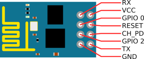
Following are the details of each of these Pins –
| Pin | Description |
| VCC | 3.3V (3.6V Max) Power Supply Pin |
| GND | Ground Pin |
| Tx | Data Transmit Pin (Works at 3.3V) |
| Rx | Data Receive Pin (Works at 3.3V) |
| CH_PD | Chip Power Down Pin. (LOW = Power Down, HIGH = Power UP). Connect this Pin to VCC Pin. |
| GPIO 0 | General Purpose I/O Pin 0 (I/O Index 3) |
| GPIO 2 | General Purpose I/O Pin 2 (I/O Index 4) |
| RESET | Reset Pin (LOW = Reset). Pull Down this Pin by connecting it to GND Pin to reset ESP8266 |
ESP8266EX Chip Pinout:

| Pin | Name | Type | Function |
| 1 | VDDA | P | Analog Power 3.0 V ~ 3.6V |
| 2 | LNA | I/O | RF Antenna Interface Chip Output Impedance = 50 Ω No matching required. It is suggested to retain the π-type matching network to match the antenna. |
| 3 | VDD3P3 | P | Amplifier power: 3.0 V ~ 3.6 V |
| 4 | VDD3P3 | P | Amplifier power:3.0 V ~ 3.6 V |
| 5 | VDD_RTC | P | NC (1.1 V) |
| 6 | TOUT | I | ADC pin. It can be used to test the power-supply voltage of VDD3P3 (Pin3 and Pin4) and the input power voltage of TOUT (Pin 6). However, these two functions cannot be used simultaneously |
| 7 | CHIP_EN | I | Chip Enable High: On, chip works properly Low: Off, small current consumed |
| 8 | XPD_DCDC | I/O | Deep-sleep wakeup (need to be connected to EXT_RSTB; GPIO16 |
| 9 | MTMS | I/O | GPIO14; HSPI_CLK |
| 10 | MTDI | I/O | GPIO12; HSPI_MISO |
| 11 | VDDPST | P | Digital / IO power supply (1.8 V ~ 3.3 V) |
| 12 | MTCK | I/O | GPIO13; HSPI_MOSI; UART0_CTS |
| 13 | MTDO | I/O | GPIO15; HSPI_CS; UART0_RTS |
| 14 | GPIO2 | I/O | UART Tx during flash programming; GPIO2 |
| 15 | GPIO0 | I/O | GPIO0; SPI_CS2 |
| 16 | GPIO4 | I/O | GPIO4 |
| 17 | VDDPST | P | Digital / IO power supply (1.8 V ~ 3.3 V) |
| 18 | SDIO_DATA_2 | I/O | Connect to SD_D2 (Series R: 200 Ω); SPIHD; HSPIHD; GPIO9 |
| 19 | SDIO_DATA_3 | I/O | Connect to SD_D3 (Series R: 200 Ω); SPIWP; HSPIWP; GPIO10 |
| 20 | SDIO_CMD | I/O | Connect to SD_CMD (Series R: 200 Ω); SPI_CS0; GPIO11 |
| 21 | SDIO_CLK | I/O | Connect to SD_CLK (Series R: 200 Ω); SPI_CLK; GPIO6 |
| 22 | SDIO_DATA_0 | I/O | Connect to SD_D0 (Series R: 200 Ω); SPI_MSIO; GPIO7 |
| 23 | SDIO_DATA_1 | I/O | Connect to SD_D1 (Series R: 200 Ω); SPI_MOSI; GPIO8 |
| 24 | GPIO5 | I/O | GPIO5 |
| 25 | U0RXD | I/O | UART Rx during flash programming; GPIO3 |
| 26 | U0TXD | I/O | UART Tx during flash programming; GPIO1; SPI_CS1 |
| 27 | XTAL_OUT | I/O | Connect to crystal oscillator output, can be used to provide BT clock input |
| 28 | XTAL_IN | I/O | Connect to crystal oscillator input |
| 29 | VDDD | P | Analog power 3.0 V ~ 6 V |
| 30 | VDDA | P | Analog power 3.0 V ~ 3.6 V |
| 31 | RES12K | I | Serial connection with a 12 kΩ resistor to the ground |
| 32 | EXT_RSTB | I | External reset signal (Low voltage level: Active) |

what are the reserved pins of nodemcu and how they can be used??
LikeLike
Hi,
thanks for the useful tuto. actually i’m using two of these guys each one with an arduino in order to be able to send commands to the two arduinos via wifi thanks to the ESP’s. i configured each module separately, so i’m wondering whether they will work together once the final circuit built and how to establish the connection between them and between the pc knowing that they will work as clients and pc as a server . and more importantly, how to send instructions (code) to arduino via wifi using the ESP.
thanks a million!
LikeLike
You can use MQTT protocol to exchange commands between these modules.
LikeLike